
Métis 2 Bobber Build

Made a start on my rear brake pedal adjuster, but had to give up when I'd almost finished, thought I had a M6 left-hand die, but I didn't.
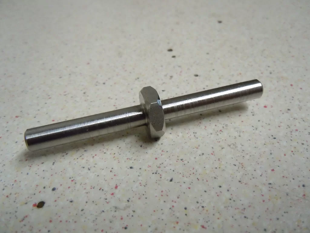
Turned a bit of 1/2" stainless hexagonal bar down to the basic shape/dimensions. It will eventually fit in the brake operating rod, when I make that & allow me to adjust the height of the pedal in relation to the footrest & my foot.
B630CB10-82E7-47EC-BDE0-7F3DDDEB37D1.webp


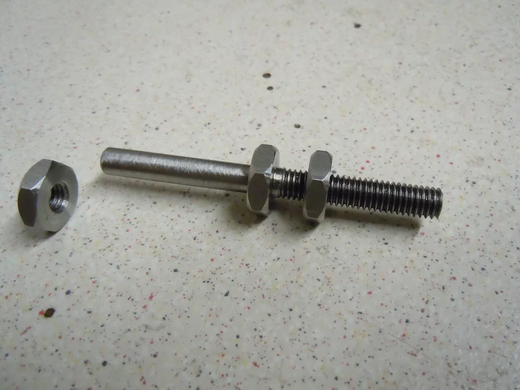
Then made the two lock nuts, (I did have a left-hand tap) & threaded the right-hand end. The left-hand end will have to wait until I can get to my local engineering supplier, unless a good quality die pops up on Ebay ! ;)
00C7873D-9C24-4A32-9534-15E3F38793F2.webp
 
Got the rear brake operating rod done today, just waiting for the left-hand die to turn up to cut the remaining thread on the adjuster. Both threads are cut in the two halves of the rod so I made a sleeve out of a bit of thick walled tube I had, just to hold the rod in position for the time being.
I had to make a couple of formers to bend the front part of the operating rod round to get the off-set between the brake pedal & master cylinder inline. The 10mm stainless steel bar that I used took some heating & force to bend, even with the extender that I also made to get some leverage on the bar & keep my hand away from the hot area !!

FAD542D4-C2DA-4CDB-9434-E09687C2B551_1_105_c.webp


The steel sleeve is just temporary, to hold the rod in position until the adjuster is fitted.

A5B05F37-6416-43F2-8433-6F97C59AD2CD.webp


The adjuster will screw into this gap & give infinite adjustment, over it's safe adjustment range.

CDE6E9DC-E17D-481C-92E1-912F3FFE4897.webp


Just the left-hand thread to cut on the adjuster, when the die turns up.

00C7873D-9C24-4A32-9534-15E3F38793F2_1_105_c.webp


All that will need doing then is to fit the rubber dust boot over the rod where it enters the master cylinder. That will need a suitable metal "grommet" making to hold the boot in position, which I will weld in place on the rod. I could have made the whole part out of one piece, but it would have taken a lot more machining & I couldn't have made it yet as I don't have the actual rubber boot !
 
Managed to get to a mate's today & collect a bit of welding he was doing for me, filling a couple of holes in the rear mudguard that I'd drilled in the wrong place & the two rear mudguard stays, that he'd finish welded the two indicator mounts to.
Once back home I got the wiring holes drilled so I can hide as much of the wires as possible. I'll double up the shrink sleeving when I do the final assembly after painting. Just as an indication of size of the indicators, the thread size is M8.

FD37E766-5CE2-493D-894B-CABD5E135793_1_201_a.webp


38F00AA0-1EB6-4C17-BDBB-EC8C41C0B231.webp
 
As mentioned in my "Another Kawasaki Project" thread, the postman delivered some parts for this project that I've been waiting for. Namely the rear brake hose, rear brake light switch & a left-hand M6 die for the rear brake adjuster.
As my wife & daughter are away for ten days sunning themselves, all my time can be devoted to "garage things", plus I've lost the sight in one eye so until I've had surgery on it to replace the lens the only way I can see properly is when I look down, which is what I do when working on bikes !!

Anyway, first job was to cut the left-hand thread on my rear brake adjuster. To keep the die square to the shaft being threaded it's common practice to keep light pressure on something like the face of a chuck.

91ECEFE8-EBBC-46C3-A8A3-29B9D166CF0F.webp


Once the die was fully threaded on the adjuster you can move the tail stock/chuck out of the way & finish the threading without that help.

130BA924-4CDB-45A3-8D4D-BEF62BDCD1A9.webp


And as if by magic, one rear brake pedal position adjuster.

8F8692B2-898C-471F-9CD1-97A691A6F918.webp


And it's now fitted to the two halves of the rear brake operating rod. Simply turning the central hex. either one way or the other will move both halves either in or out to either lift or lower the brake pedal. Just need to find a suitable rubber boot now to keep the road grime out of the master cylinder.

465E088C-9705-40CD-9474-B0481DA29275.webp


The postman also brought the newly swaged rear brake hose & brake light pressure switch. As this bike is using a lot of Harley aftermarket parts, threads tend to be either UNC or UNF. The rear master cylinder requires a UNF threaded pressure switch with a short thread as opposed to the more commonly available metric longer threaded options, hence the wait. Brake will now just need bleeding up when the final build commences !
Dry break coupling at the caliper end makes wheel removals much easier, plus they look trick !! :love:

534566B3-2ED9-4F68-ABC5-F20EDADB4435.webp
 
Managed to get to a mate's today & collect a bit of welding he was doing for me, filling a couple of holes in the rear mudguard that I'd drilled in the wrong place & the two rear mudguard stays, that he'd finish welded the two indicator mounts to.
Once back home I got the wiring holes drilled so I can hide as much of the wires as possible. I'll double up the shrink sleeving when I do the final assembly after painting. Just as an indication of size of the indicators, the thread size is M8.

View attachment 103729

View attachment 103730

Could you not hide the wires? It's very OCC like that tbf :unsure: even Uncle Bunt was hiding them completely 40 years ago 👀

Even better you could ditch them altogether 🤷‍♂️
 
Could you not hide the wires? It's very OCC like that tbf :unsure: even Uncle Bunt was hiding them completely 40 years ago 👀

Even better you could ditch them altogether 🤷‍♂️
Uncle Bunt didn't have indicators on his bikes in them days !!
It would be impossible to hide the wiring completely, considering where they are mounted & where the wires need to get to. As a Tesi owner you're not really well placed to be offering advice on neatness Exi ! :ROFLMAO::ROFLMAO:
 
Uncle Bunt didn't have indicators on his bikes in them days !!
It would be impossible to hide the wiring completely, considering where they are mounted & where the wires need to get to. As a Tesi owner you're not really well placed to be offering advice on neatness Exi ! :ROFLMAO::ROFLMAO:
You could consider where you mounted them, c’mon you’re better than this 🤷‍♂️

Don’t be a jelly belly about the Tesi 😍

Beer 🍻 now, laters mittens 🙂👍
 
I extended the cables for the two rear indicators & the rear tail/brake light today. Despite really struggling with my defective eye I managed to get the cables joined up & shrunk wrapped.
First picture is the tail light & indicator ON, second picture is with the brake light ON too, although the brake light doesn't look much brighter than the tail light in these pictures it is "in the flesh", but the indicator is blinding by comparison & considering it's size, quite remarkable !!

AC68B808-0015-48D6-82FA-9FEFA0630CC0_1_201_a.jpeg


4AF5ABC8-1F3D-40A2-B02B-A8C98A4FF9AF_1_201_a.jpeg


Also, tapped a hole for a P-clip to hold the rear light wiring in position.

C7324146-DF3E-4136-A790-9E5C93B314B5_1_201_a.webp


Just having a beer now to celebrate not smashing anything as I was getting frustrated with my eye !! :ROFLMAO:
 
Last edited:
The ferrule bends arrived today from Venhill so I could have a look at what I might need for my throttle cable. I also needed to check for clearance between this bend & the right-hand fuel tank. They had two bends with 6mm threads that looked suitable on their web site so I bought one of each to physically check them out. The bend I've used is labelled as a Yamaha part & was the best option I could find with a 6mm thread to go in the throttle housing.
When I shortened the handlebars that I'd been supplied with when I bought my forks, I was a bit concerned that I might have made them a little too short & the throttle cable was going to be a bit close/touching the tank. Turned out I was right so I had to extend the handlebars a little, only about 50mm each side. So I made a couple of "slugs" to support the two extensions. Trouble is because my left eye is useless at the moment, until I've had an operation to replace the lens, trying to TIG things in place is proving to be very difficult, so much so that it's not worth trying at the moment as it creates more work tidying up the shit welding !!

038E4CA0-0C18-4A46-9638-FFEA5AAE58C8.webp


Anyway, the throttle cable routing I have in my head should be OK now, just need to arrange a visit to Venhill at some point & get a couple of custom throttle cables made up.
On the first bike I managed to find a suitable Harley throttle cable that worked, but this build is a bit different & there doesn't seem to be a current Harley cable that will work, so the custom route is the best route I think. Most Harley throttle cables are either a UNC thread or a plain hole with a circlip groove.

Also, checked out my side stand, which also looks like it will be OK, once I can tack the mount in place. The mount, side stand & return spring are all Triumph Daytona items. The side stand in the picture is one from my first build that I'd cut a bit short so I'm just using it for a guide at the moment, the final version will be made from the unmolested stand in the background.
Unlike Exi's shit "side-stand in your pocket", this one will be thought out & properly welding in position & a thing of beauty ! :ROFLMAO:

66DF104A-F6A0-4047-A3C9-ACA1F51EA1FF.webp
 
Having a side stand saves me looking around for high kerbs, tree trunks, walls, etc to lean it on. I did think about having a scrappy bit of conduit in my back pocket, but figured sooner or later I loose it ! :ROFLMAO:

Powder coating it blue, RAL5002 to be exact !! :ROFLMAO:
 
Having a side stand saves me looking around for high kerbs, tree trunks, walls, etc to lean it on. I did think about having a scrappy bit of conduit in my back pocket, but figured sooner or later I loose it ! :ROFLMAO:

Powder coating it blue, RAL5002 to be exact !! :ROFLMAO:
I've got an official Yoshimura Botty Bum Bag for mine, couldn't find a Moriwaki one 🤷‍♂️
 
Managed to get the engine/primary drive/gearbox lined up today. I made some temporary spacers & now I know what size spacer I need I'll get the standard size one I have machined to suit.

379F89B0-1A69-4740-AE68-C7476AD6926D.webp


The spacer will fit between the engine crankcase & primary drive motor-plate. The standard spacers that are available for BDL primary drives are 1/4", 1/2", 3/4", 1", 1.5" & 2". Mine needs to be 4.5mm so I bought a 1/4" one, which I'll get machined to suit.

8B9CB8C3-2B5F-429E-A29A-263CA9358B3A.webp


This is the standard spacer, hanging on the gear lever, shaped to follow the shape of the crankcase & motor-plate.

1C61015B-D235-443B-9FC9-0F8E8A285AD5.webp


Now the primary drive is fitted the next job will be to get the side stand mounted. I'm using a Triumph Daytona assembly as it worked quite well on the other build. I'll use the un-shortened stand as this bike has a little bit more ground clearance than the other one, so consequently the stand will need to be a little longer. The one I've got fitted at the moment is just a spare one I had.
I'll have to wait now though until my eye is sorted, can't see well enough to weld at the moment !! :LOL:

7F14121C-D5EF-443F-9149-72EB80632AC8.webp


114F6DD3-F628-4F21-9E36-3280668E4E3A.webp
 
Realised a while ago that I needed to make some slightly longer steering stops for the fork legs to stop the steering damper fouling a couple of nuts, which are holding the leaf springs together.
Just made two 5mm longer stops today out of a bit of black Delrin bar & swopped them over with the old ones. They just screw into the mounts of the inside of the two for legs so a quick job really. The steering lock is still quite good even with these fitted, which is a lot better than my 750SS !! :ROFLMAO:
I left the mating mounts in either side of the frame top tube as they were, couldn't be bothered splitting the increase between the two halves !! ;)

E49658C1-DDD7-4A78-BD54-318F61E0D715.webp


9AC35577-ADF8-4994-B1A3-D6CB13A02A97.webp
 
Spent the day today aligning the engine/gearbox/primary drive/rear wheel. Started around 10am & finished at around 5pm, but now everything is aligned & it's now ready to have the exhaust made up. There are other jobs to do, but the exhaust is a job out of my control really & the engine needed to be positioned correctly before it is made. A small amount of mis-alignment at the engine end can have huge effects at the "silencer" end !!
I'm hopefully going to get OJZ Engineering to make this exhaust too, (Lance did the first Métis & his welding is something to behold), providing he's still working !!

CA1AE12E-2B43-4978-93C1-9FE4873A064E.webp


5A399AE5-24B9-4D23-8B40-673D0BA83708.webp


9F2715D8-31F1-4171-AB25-3BF047A8F191.webp


It's a bit soul destroying really that I've spent all day doing something & the bike looks no different to how it looked this morning before I started !!
At least once the exhaust is done the remaining jobs are jobs that I will be doing, bar one, the painting !!
The engine drive pulley has to be aligned with the clutch, but I can't do that until the alternator is bought/fitted as it sits behind the engine pulley. The magneto ignition needs buying/fitting, but that is just a money issue ! The top engine mount also needs finishing, but I'm going to leave that until the final build, just in case anything is out of alignment & it won't stop the bike being basically finished as the top engine mount is just a quick bolt on job.
Other than that there some final welding to get done when the bike is stripped for painting.
 
Starting to look finished now !
Need to save a bit of money & then get the exhaust made now the engine is in its final resting position, i.e. aligned with the primary drive, gearbox & rear wheel.
Next year at the latest 🤞 That will make it six years in the making, far quicker than Exi's epic !! 🤣

A32E0FB8-1179-4F8B-B33C-DF237F071D86.jpeg


BA641AE7-C673-46FF-924A-4E2A0E3B60E4.jpeg
 
Last edited:
Why have you put the Harley cup holder behind the front wheel :unsure:
To keep my beer cold when I travelling at high speed, obviously !! :ROFLMAO:
Who's Eli? he sounds extremely slow :unsure:
That's you Exi, when auto-correct gets involved !! :ROFLMAO: And you are slow, by the way, are we there yet ? :unsure:
So oil doesn't drip into from the engine :unsure:
S&S engines don't leak oil, they've been put together properly !! ;)
 
To keep my beer cold when I travelling at high speed, obviously !! :ROFLMAO:

That's you Exi, when auto-correct gets involved !! :ROFLMAO: And you are slow, by the way, are we there yet ? :unsure:

S&S engines don't leak oil, they've been put together properly !! ;)
You could be a politician with all your lies 👀 :unsure:🤪
 
Got the two starter-motor to battery cables made up today. That's the first bit of "real" wiring done ! :ROFLMAO: Time wise it's still a long way off, but it will still be quicker than Exi's epic !! ............ talking of which, "are we there yet ?" :sleep:

E2B839F1-0240-4D06-B407-45F680CE75F5.jpeg
 
Last edited:
Got the two starter-motor to battery cables made up today. That's the first bit of "real" wiring done ! :ROFLMAO: Time wise it's still a long way off, but it will still be quicker than Exi's epic !! ............ talking of which, "are we there yet ?" :sleep:

View attachment 113865
You slow Guinness 🤷‍♂️ 🤷‍♂️ 🤷‍♂️ this is approaching 20 years if you include the first failed prototype :oops: vs my 16 months and I had an engine to build 🥳
 
Back
Top Bottom