Eelco's Darmah

oil restrictors

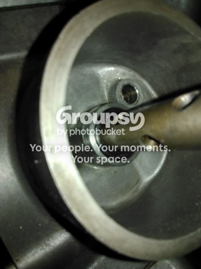
MMT i coming round tomorrow to tackle the gearbox so I decided to clear a space to work in and got distrarcted, as you do. I need to restrict the oil flow to the heads and so drilled out a couple of Allen bolts, thinned down the tops and tapped them into the oilway up from the bottom of the barrels.
restrictor_zpsc8b17673.jpg

Since they are effectively trapped in the joint as the hole in the case is smaller they cannot drop out. I drilled them at 2.5 mm which is slightly bigger than Kevin Bracken recommends.
 
In a rare moment of sunshine I pulled everything out of the garage and MMT helped build the gearbox back up again. The spacers/shims went back in in completely different places based on his knowledge of gears and 'feel' It was a bit like watching 'Merlin' without the CGI. He even modified my circlip pliers to work on the funny clips and saved another set of fingernails as a result. then he gave me a bollocking for letting the cases get dirty, and has made me promise to get busy with the cleaner before we close them up again.
As we discussed the oil filter and the 'German' O-ring seal parts that Mr Vacant possession kindly sent me, MMT wondered if it might not be possible to manufacture an adaptor (Instead of the centre-post) so that you could use a screw-on filter instead of the centre-post/cartridge/ tin cover-type. I suppose if you found the correct size of filter that might not be a bad idea but I think I'll save it for next time or until he gets access to better machinery in this post-job phase.
 
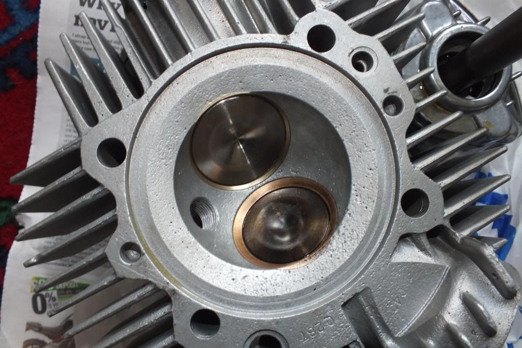
We had a good look at the cylinder-heads which are definitely of the early, small inlet stud-spacing variety. They also seem to have quite small valves even though they do fill the space available. MMT suggested smaller carbs would work better and I'm tempted to agree but I've already re-built the 40s and I know that if i ever sold the bike they'd make it more sought-after. Guess I'd better stop dreaming and concentrate on cleaning!
 
Kind Mr Vacant possession sent me a couple of special O-rings and a pair of the rings that he has had turned up in order to provide a high-pressure seal for oil which is now entering the filter bass-ackwards. I suggest that anyone completing the same modification contact him as they are very useful insurance.
oilfilter5a_zps95b27d03.jpg

oilfilter5_zpsca656e20.jpg

The larger ring fits over the step at the bottom of the centre-shaft, enclosing it and the O-ring. The rings are sized slightly smaller than the O-ring to all the correct amount of compression for a seal.
oilfilter3_zps768534f9.jpg

The bottom face of the filter sits against the O-ring and the whole thing is surrounded by the now unused rubber sealing washer - I may look to see if this obstructs the exit hole for the oil in which case I'll remove it from the bottom filter-face -

oilfilter2_zps406c1507.jpg


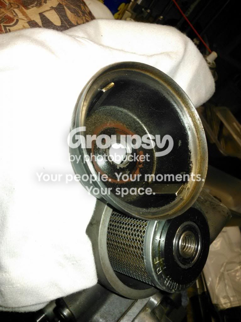
As an added precaution I bought some ultra strong magnets from e-bay and, when I'd prised them out of my steel post-box, I bonded a couple to the inside of the filter-top. Vacant Possession recommended this to catch the fine bits that the filter won't.

oilfilter1_zps78815718.jpg
 
As an added precaution I bought some ultra strong magnets from e-bay and, when I'd prised them out of my steel post-box, I bonded a couple to the inside of the filter-top. Vacant Possession recommended this to catch the fine bits that the filter won't.
FX: Errrr... I hope you didn't mistake me for someone who knew what he was talkin' about! I must admit I am doing something very similar but I hadn't yet worked out/decided how to attach the magnets; You don't hang about!

Looks pretty good tho'. I am guessing 'ignition' isn't too far away now; I am most envious as I regard my pile of bits, I haven't even got my bottom ends back from Godden yet:toilet:.
 
The bottom face of the filter sits against the O-ring and the whole thing is surrounded by the now unused rubber sealing washer - I may look to see if this obstructs the exit hole for the oil in which case I'll remove it from the bottom filter-face -
Yes, both those washers have gone on mine; The bottom one never does anything on an unmodified oil system and the top one just gets in the way with the (better) 'O' ring system.

How has the oil pump->Bundy->bevel support/filter lower bit gone?
 
The magnets attached themselves to the steel top. The bonding was just a belt+ braces thing. I took the oil pump off (again) and replaced the spring with the one you kindly sent. You were right, it was quite a bit stiffer.
Ignition is a long way off, still, since I reckon a spark is one of the things that have gone missing in the last 20 years of inactivity. One of the first things I noticed wa that the lead to the starter had been cut so I am expecting trouble there, too. Thank goodness for kickstarts.
 
I pulled-off the lower rubber washer but left the top one on. I found filters at £1.59 each on ebay so bought 3. Cleaned out the cases after cleaning the gasket faces again. Put the crank in and then the cases back together. Started to put the oil-pump gear on and then realised the crank was in the wrong-way around. how I laughed! the cases came apart a lot easier this time as I realised it was the layshaft sticking in the bearing that was holding things back.
So effectively I am back where I started!
 
the cases came apart a lot easier this time.......

you must be getting good at that by now ;) :) interesting following this thread.... apart from removing the sprocket cover, i've managed to avoid delving into the oily bits of my Dramah, but thats mostly because i've approached it the wrong way round and concentrated on the cosmetics first.. :o it was running ok when i got it, so i'm sure it will be fine when i eventually fire it up.. !!!! :D
 
... mostly because I've approached it the wrong way round and concentrated on the cosmetics first.. :o
I think you have got it entirely the right way round, best to ride 'em when you can! Just looking out of the window wistfully...

I didn't want to take mine off the road, was quite happy to wait. Unfortunately the waiting came to an end shortly after I swung my leg over it, the only thing I am happy about is I didn't leave it too long once the ominous signs presented themselves.

I can' wait to get it back on the road, engine is booked in with Pietro for assembly at the end of April.

Hat's off to Martin for doing all the work himself. Even though I have the manuals and probably have a good idea what I should do, putting the crankcases together finally,watching that thin sliver of black shrink until it's closed and tightening the two halves together is a step too far for my confidence. Tony Brancato used to run courses... I wish I'd gone on one.
 
You could learn a lot from watching somebody who'd done it a lot, I guess. I have got a little further today but hava a question if anyone has used a Surflex clutch before: My haynes manual mentions that on the 86O there is a small washer at the base of each clutch spring. I don't have such a thing but wondered if the surflex springs don't need one?
My second question concerns the bits that run through the centre of the gearbox to push the clutch. There are a lot of them but I guess they are there for purpose. I appear to be short a 5/16 ball! I think it must have run off at some point. Ah well,
Whilst a bit bored I looked at the cylinder heads and see that I have 42mm and 38mm valves but there seems to be a bit of confusion over what was standard. I have opened up the port at the flange to match the rubber gasket which matches the inlet manifold. My engine was one of the last to feature the narrower spacing between manifold studs and the ports at the manifold face were definitely small. interesting!
 
Now I'm really confused! I've looked at different manuals and articles and there is a little discrepancy in the clutch rebuild order. I have one plate with its inner drive teeth slightly bent over and a plate with bent over outer tangs. Some accounts put these first or last and talk about them being bent in or out. I usually take 'out' to be from the vehicle centreline, but does anyone know the absolutely correct order and orientation?
 
I have no washers under my springs, clutch is a new surflex bought from Andrew. They are held in place with a screws & washer. The ball is easy to get. Worth having a quick shufti at all the bits to make sure they aren't too worn; They are easy to get out in future with the engine in situ so no worries there.

Looks like my valves are 36/40mm.

DSCF6454.jpg
 
Last edited:
As I recall the plain plate with the angled tang goes in first with the angle out. The washers below the sprigs will increase the preload slightly from having none. As the bevel clutches have a tendency to slip under load I'd fit them. The clutch pushrod as you've noticed is made up of a series of short lengths, rollers and a ball bearing. As long as you achieve an overall length that gives you sufficient lift of the plates the exact order probably won't matter much. I can't help with the valve sizes though.
 
Now I'm really confused! I've looked at different manuals and articles and there is a little discrepancy in the clutch rebuild order. I have one plate with its inner drive teeth slightly bent over and a plate with bent over outer tangs. Some accounts put these first or last and talk about them being bent in or out. I usually take 'out' to be from the vehicle centreline, but does anyone know the absolutely correct order and orientation?
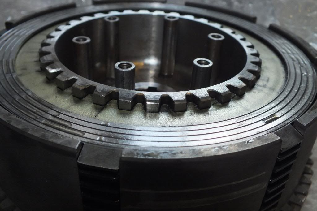
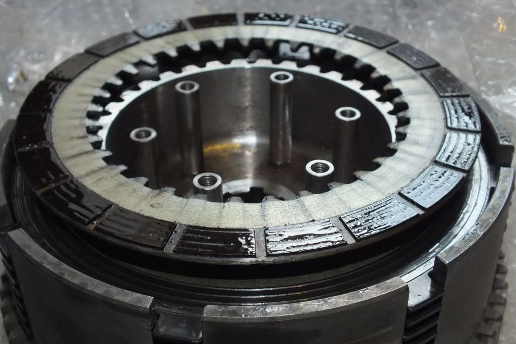
It just so happens I have my beautiful clean clutch in a box next to me, stacked in the same order in which it was removed from the bike last year. You can clearly see the top plate has the tangs pointing down:-
DSCF6456.jpg

Here it is with the pressure plate removed...
DSCF6461.jpg

Which doesn't really show where the teeth of the first friction plate are pointing, this does...
DSCF6462.jpg

However my clutch used to be *very* snatchy and I think I can see why. Any bevelheads who know otherwise, please speak up but I think the teeth should be pointing down to maintain contact as the clutch is disengaged, like this:-
DSCF6463.jpg


That's my two pennies worth.
 
As I recall the plain plate with the angled tang goes in first with the angle out. The washers below the sprigs will increase the preload slightly from having none. As the bevel clutches have a tendency to slip under load I'd fit them. The clutch pushrod as you've noticed is made up of a series of short lengths, rollers and a ball bearing. As long as you achieve an overall length that gives you sufficient lift of the plates the exact order probably won't matter much. I can't help with the valve sizes though.
What you are saying makes complete sense and also agrees with the workshop manual.
WorkshopManualClutchReassemblyPageG-18.jpg

Here is an old clutch centre stuffed in a new clutch basket. Looks like with clearance from the mainshaft, the friction plate with the teeth pointing upwards does go at the bottom - and the manual agrees. I would be thrilled if my clutch stopped being a dragging monster and it could well be because of incorrect assembly.
DSCF6475.jpg
 
What a wealth of knowledge! My workshop manual says the same but I have seen photos which, like Vacant's are opposite. I have a feeling that the confusion arises from having badly reproduced line-drawings couple with confusion between drive and driven plates in the english translations.
So far as the springs go, I aim to check that the run-out on the clutch cover-plate, as recommended in a recent Classic bike feature. I may do that without washers under the springs to make life easier before seeing how much shimming is needed and where. I have also heard the stories that twin clutches are prone to slipping and that people fit 450 springs but, since the clutch is easy to get-to, will do as MMT always suggests and 'get it running, first'
thanks for all your help.
 
... I have also heard the stories that twin clutches are prone to slipping and that people fit 450 springs but, since the clutch is easy to get-to, will do as MMT always suggests and 'get it running, first'
thanks for all your help.
Mine used to slip but it looks like that was more of my choice of oil containing additives that are not suitable for use with wet clutches. I have replaced my clutch and now use only oil I carefully vet as not providing extra slippery stuff which shags my wet clutch.

My clutch now does not slip and is a perfectly standard (Surflex).
 
That's a lovely clutch basket and straight-cut gears there. I tried a dial-gauge on the built up clutch and spent a while shimming but couldn't get the plate to spin any flatter than it did already. I think that there may be an easier way using locking nuts on longer spring bolts like my old Mini tappets, perhaps. Anyway it appears that the clutch pushrod bits (even when I added in a mild steel spacer to replace the missing 5/16 roller) are too short to push enough. Even adding a spacer so big that the 'bullet' piece was nearly falling out of its hole in the centre of the shaft was only just enough. MMT has a bit of silver steel rod so maybe he can knock me up a longer bullet which will leave more in the hole for support. Then I might have chance to extend the clutch arm by 15mm or so and get an easy-pull whilst still having enough 'push' distance on the rod. I'll get him to cast his eye over it first, in case I've made another 'assumption' despite that I popped on the pistons and it's barrels next, maybe when I get back at the end of the week.
 
Whilst in barcelona I managed to make a diversion into the ne museo Moto in the Bari Gotic for half an hour. They are having a temporary exhibition which features the 24 horas Montjuic and has the 1980 winning 'NCR' bike. It has been in lots of books and articles, talking about the lovely detail touches. I was taken by the double pins in the calipers on little springs to help with pad changes. For students of oil-ways such as vacant Posession and Myself, the oil feed came off the cam-cover and returned into the top of the filter housing. I noted the use of orange instant gasket - very '70's!


Instant gasket? Yuk! Looks like the engine builder was a real instant acolyte. I love the pictures but won't be fitting the interesting pad quick change system anytime soon ;-)

I hope your build is coming along, I heard the first cuckoo (go Delius!) on Sunday.
 
Thanks very much for that. I used to have music lessons in the 'Delius room' at school so I hear where you are coming from. Unfortunately I don't think that the motor will be going again any time soon but I'm happy to keep plodding on. The instant gasket was pretty common at one time in Endurance racing as it made for quicker mid-race rebuilds. If you greased up one of the covers then assembled and dissassembled then cleaned off, you could get a sort of permanent gasket that might save a bit of pit-time for, for example, a clutch change. With hindsight it looks crap but then it was 'trick'
 
There are just too many good things to buy for bevels!
I have bought some 5/15 x 5/16 rollers and bearings so I've got a few left over if anybody needs one! I still think that the 'bullet' is hanging too far out of the shaft centre but am prepared to be proved wrong. it may be that the inside of my operating arm is sacrificially worn.
I popped on the barrels using a ring clamp I bought to rebuild an old car motor years ago. The heads were next, at which point I realised that the studs were sticking too far out of the cases and catching on the bottom of the cam castings. I had been wary of winding the studs in further as they were getting tight but I guess I'll have to do that. In any case the nuts seem to be bottoming out before the head clamps down so i need to pull stuff off and do a bit of measuring. Still, even though as usual its a case of one forward and two back it was good to see the thing looking more complete.
 
I was right about the studs and ended up winding them all out and in again. Both heads had their combustion chambers wire brushed to get rid of the carbon from what looked like rich running or lots of oil in the wrong place. The front squish band was showing signs of having been peppered with something hard but its all going back as it is. i have taken the bearing out of the ignition cover and now have to find the new one I bought about a year ago. The original is of the 'blind on one side' type recommended to keep oil in but has appreciable play in it so it's going in the bin. Still a long way off but it looks like an engine, now.
 
Most cool! Looking forward to a picky of the unit.

When you've done some riding and decided you can't part with it, Tony Brancato will modify your heads to 40mm throughout, just so you don't get bored next winter ;-)
 
But with Tony it's all about talk, not power (or so I've heard, I've never spoken with the man)
When I opened up the inlets I just smoothed out the opening up to about 1/2 inch in, being careful not to upset the transition around the short (bottom) side into the valve. I'm not sure that opening up any more would really be such a good idea, since gas speed will be slow enough through those big 40's without giving the lungs too big a straw to suck through. I wrote an email yesterday to the Czech ignition wizards to make a plan in case my ignition is kapput when I get that far. There are many different ignitions to choose from ( including the successor to the RITA) but I haven't had very good experiences with fully programmeable software so I may go for the simplest or even try to fix the Bosch (assuming it's bust - one of the boxes of bits I got with the bike had a used Bosch ignitor 'box' in it so I have my fingers crossed.
 

pick-ups - note missing screw and 'special needs' connector

This is the hole I drilled into the plug to allow some oil to reach the crank. Thanks to the article elsewhere in DUN I checked that my oil-hole was being (almost totally) blocked by the plug. Phew, narrow escape.
 
Back
Top Bottom